Week 6: Electronic Input Devices
Capacitive Sensing & Soil Moisture
This week, Felicia and I both decided to apply the capacitive sensing examples from class to our shared inability to keep houseplants alive due to either over or under watering them. Since we're also working on the final project together, and we're both interested in drawing connections between nature and technology, we thought it could be a fun and useful exercise to build our own soil moisture sensors and compare them with the soil moisture and water level sensors that the lab provided.

Homemade "Soil Moisture" Sensor
The homemade "soil moisture" sensor employs the logic of the tx-rx measurement method from class. Basically, if the two prongs of an
object are wrapped in capacitive material (in our case, a thin, adhesive film of copper), and the prongs are connected to ground and voltage
respectively, we can measure the strength of the electric field between the two prongs/electrodes. Additionally, if these prongs are submerged
in water - or better yet, soil saturated with water - we can explore how the soil's water saturation affects the capacity reading we get.
This is why the homemade sensor roughly relates to soil moisture, and why it's compelling to compare it with off-the-shelf sensors.
Rough Experiment Design
For each sensor type, we tried to collect the following measurements:
- Air (Control): Sensor reading in room environment
- In Water: Sensor reading in cup of water
- Out of Water: Sensor reading once it's taken out of the water
- Plant - Dry: Sensor reading in dry plant
- Plant - Wet: Sensor reading in watered plant (increased watering for some instances)
Red: Water Level Sensor
In hindsight, using the water level sensor may not be a useful or compatible point of comparison for this exercise. I only discovered it measured water level as opposed to moisture upon building out this section of the website. Oops! However, we did use it, and I'll list our findings here.
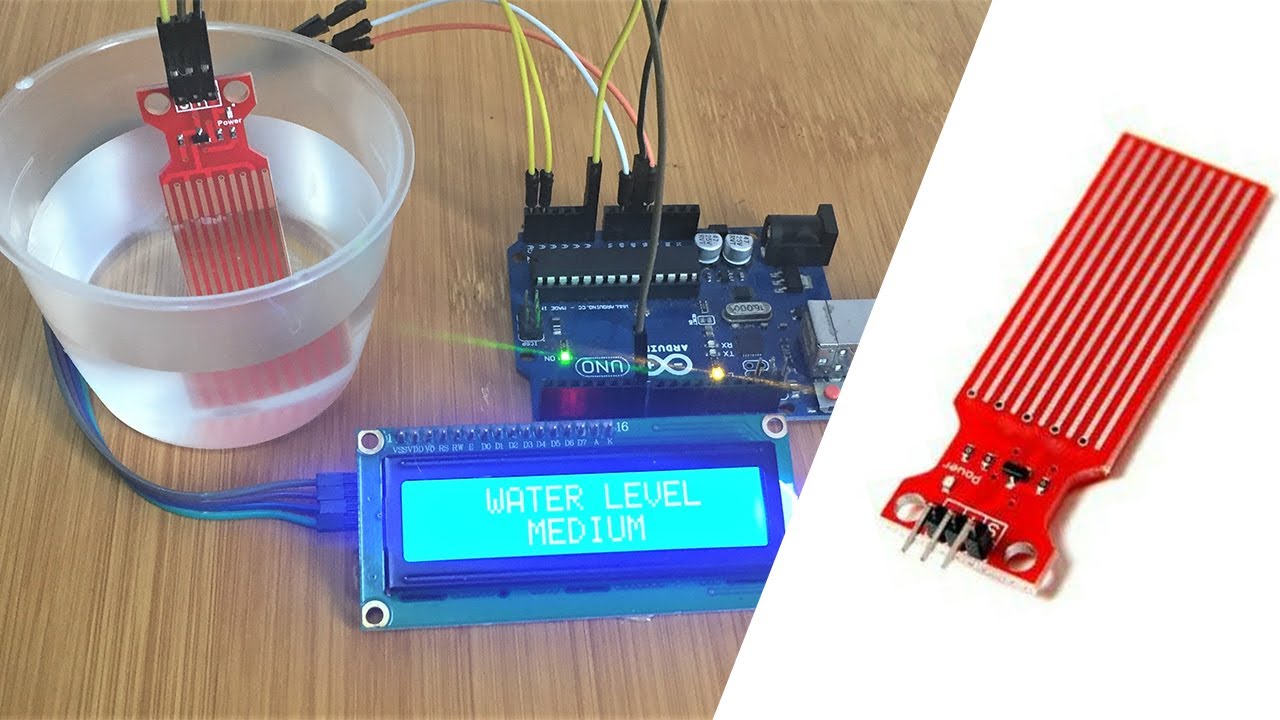
Arudino Code & Process
#define POWER_PIN  7
#define SIGNAL_PIN A5

int value = 0; // variable to store the sensor value

void setup() {
   Serial.begin(9600);
   pinMode(POWER_PIN, OUTPUT);   // configure D7 pin as an OUTPUT
   digitalWrite(POWER_PIN, LOW); // turn the sensor OFF
}

void loop() {
   digitalWrite(POWER_PIN, HIGH);  // turn the sensor ON
   delay(10);                      // wait 10 milliseconds
   value = analogRead(SIGNAL_PIN); // read the analog value from sensor
   digitalWrite(POWER_PIN, LOW);   // turn the sensor OFF

   Serial.print("Sensor value: ");
   Serial.println(value);

   delay(1000);
}
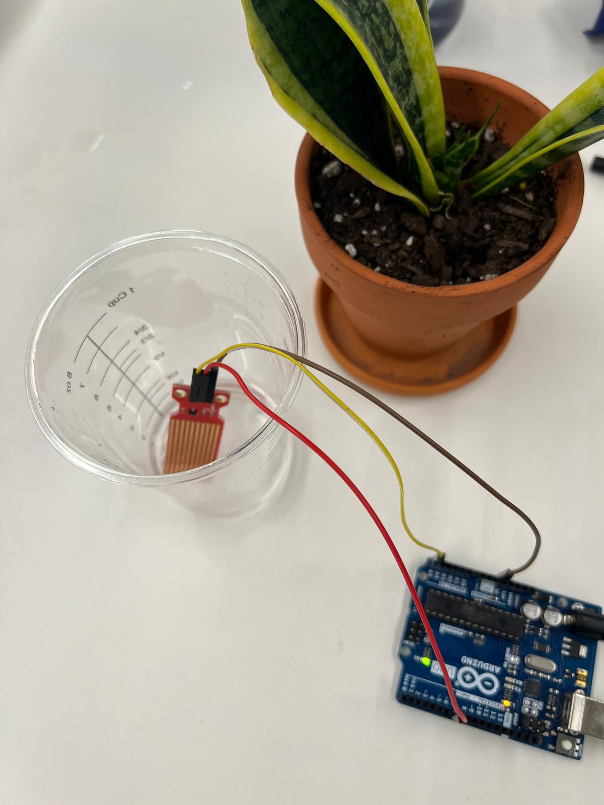
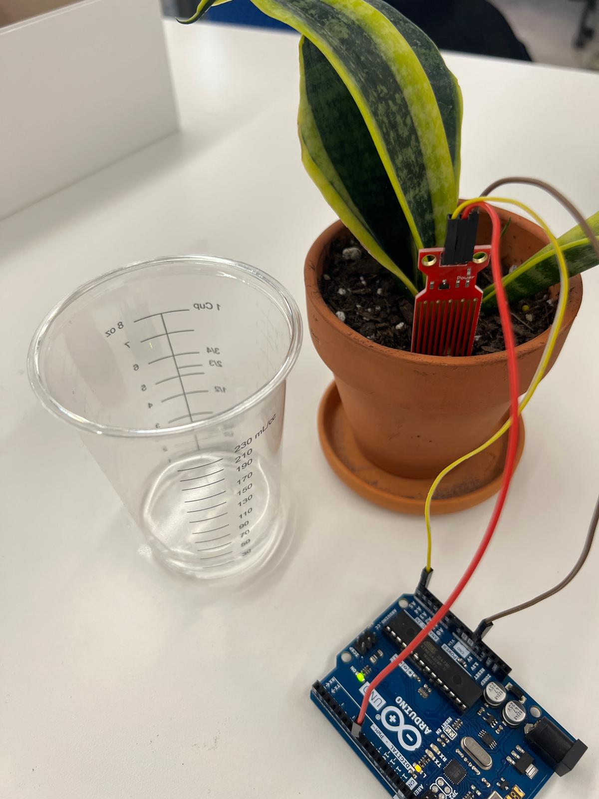
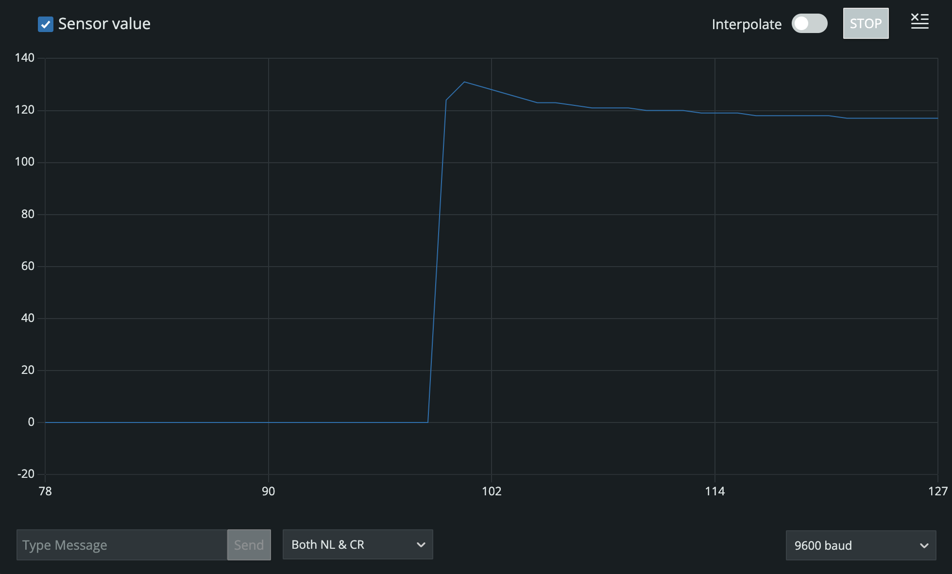
| Experiement | Capacitive Value (Arduino) |
|---|---|
| Exposed to air | 0 |
| Submerged in water | 117 |
| Taken out of water (not dried) | 33 |
| Taken out of water (dried) | 0 |
| Stuck in plant | 11 |
Homemade Soil Moisture Sensor
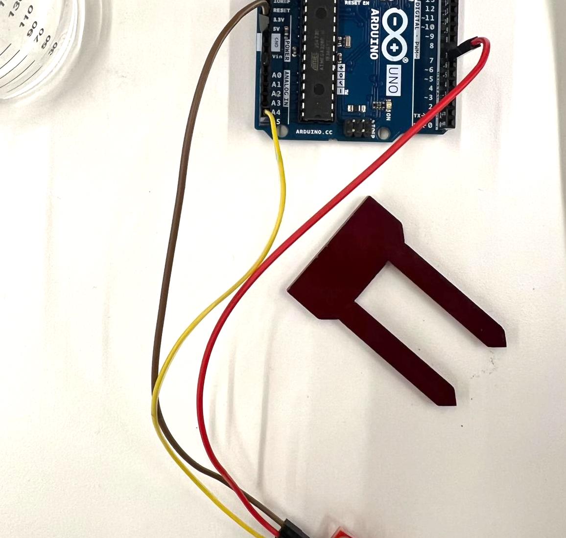
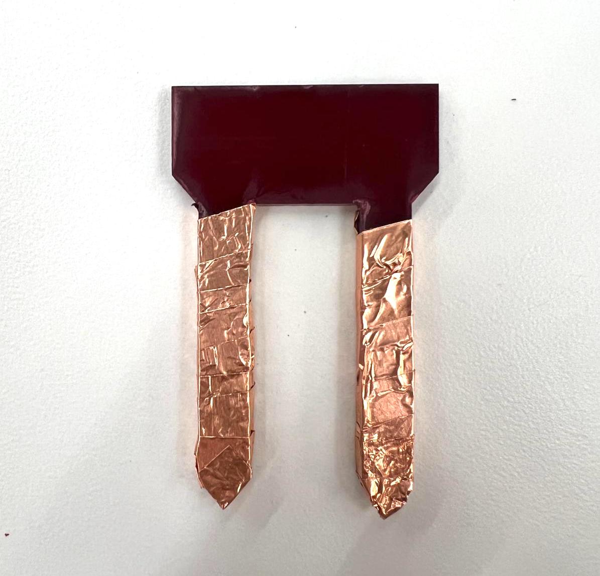
After testing the water level sensor, we decided to try out both of our homemade soil moisture sensors. We
both designed small, two-pronged objects using the calipers and proceeded to laser cut them onto 1/4" acrylic, then
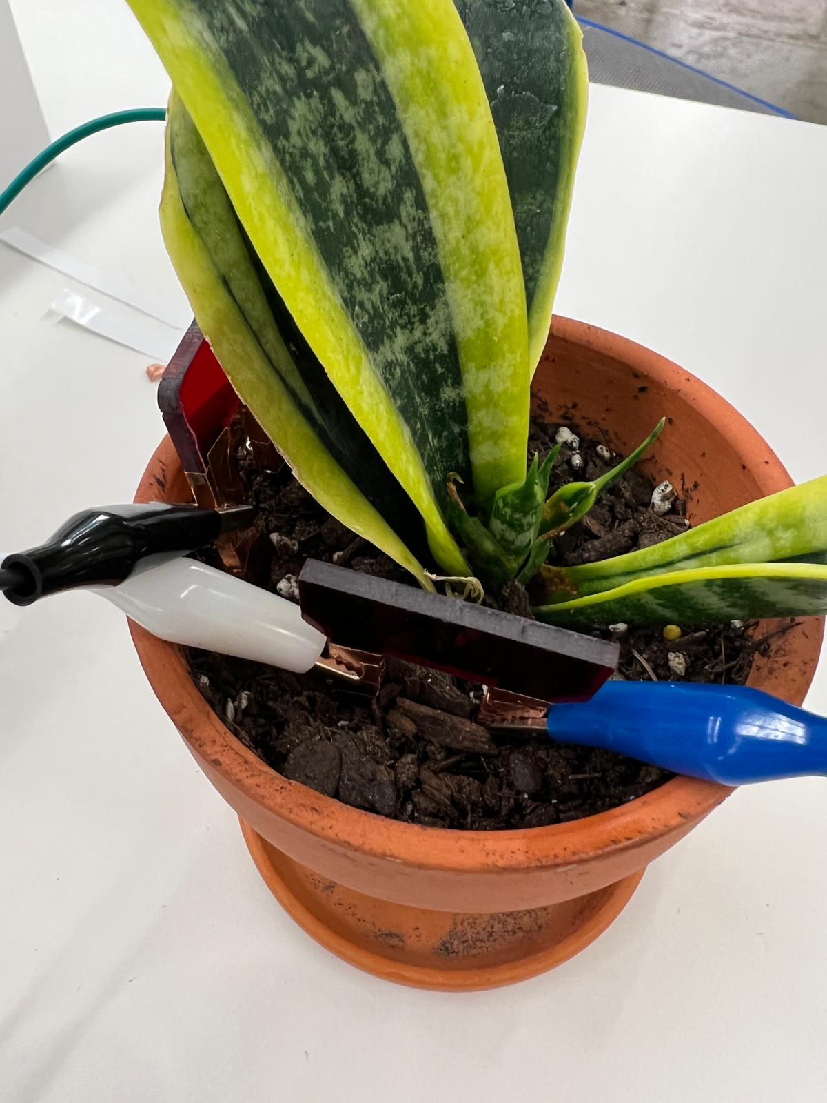
wrapped them in the copper film and used the alligator clips to attach them to power and ground using our microcontrollers
and breadboards. We utilizes the example code from class, listed below.
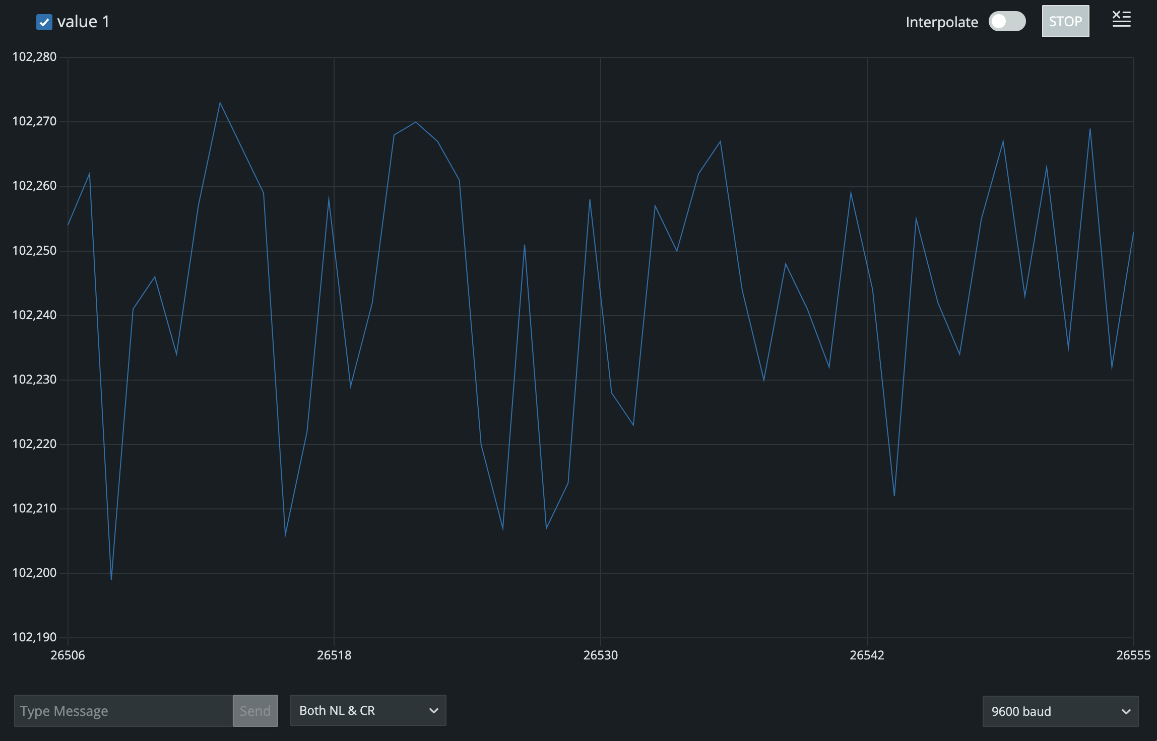
Our results were interesting in that the sensors "worked" but we noticed that their capacity might have a ceiling around 102,000, because
it didn't make sense that the sensors being submerged in water and then being in the wet plant would have the same values.
Arudino Code & Process
    long result;
    int analog_pin = A3;
    int tx_pin = 4;

    void setup() {
        pinMode(tx_pin, OUTPUT);
        Serial.begin(9600);
    }

    void loop() {
        result = tx_rx();
        Serial.println(result);
    }


    long tx_rx(){

      int read_high;
      int read_low;
      int diff;
      long int sum;
      int N_samples = 100;

      sum = 0;

      for (int i = 0; i < N_samples; i++){
       digitalWrite(tx_pin,HIGH);
       read_high = analogRead(analog_pin);
       delayMicroseconds(100);
       digitalWrite(tx_pin,LOW);
       read_low = analogRead(analog_pin);
       diff = read_high - read_low;
       sum += diff;
     }
      return sum;
    }
| Experiement | Capacitive Value (Arduino) |
|---|---|
| Exposed to air | 3,150 |
| Submerged in water | 102,300 |
| One sensor stuck in plant | 5,900 |
| Both sensors stuck in plant | 3,650 |
| 10mm water added to plant | 102,200 |
| 20mm water added to plant | 102,200 |
| 30mm water added to plant | 102,300 |
| 60mm water added to plant | 101,200 |
Black: Soil Moisture Sensor
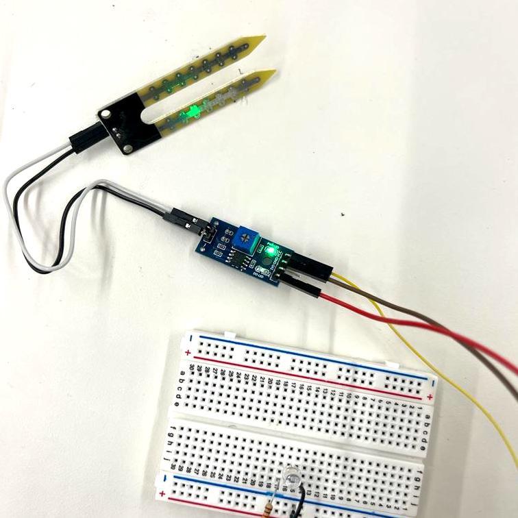
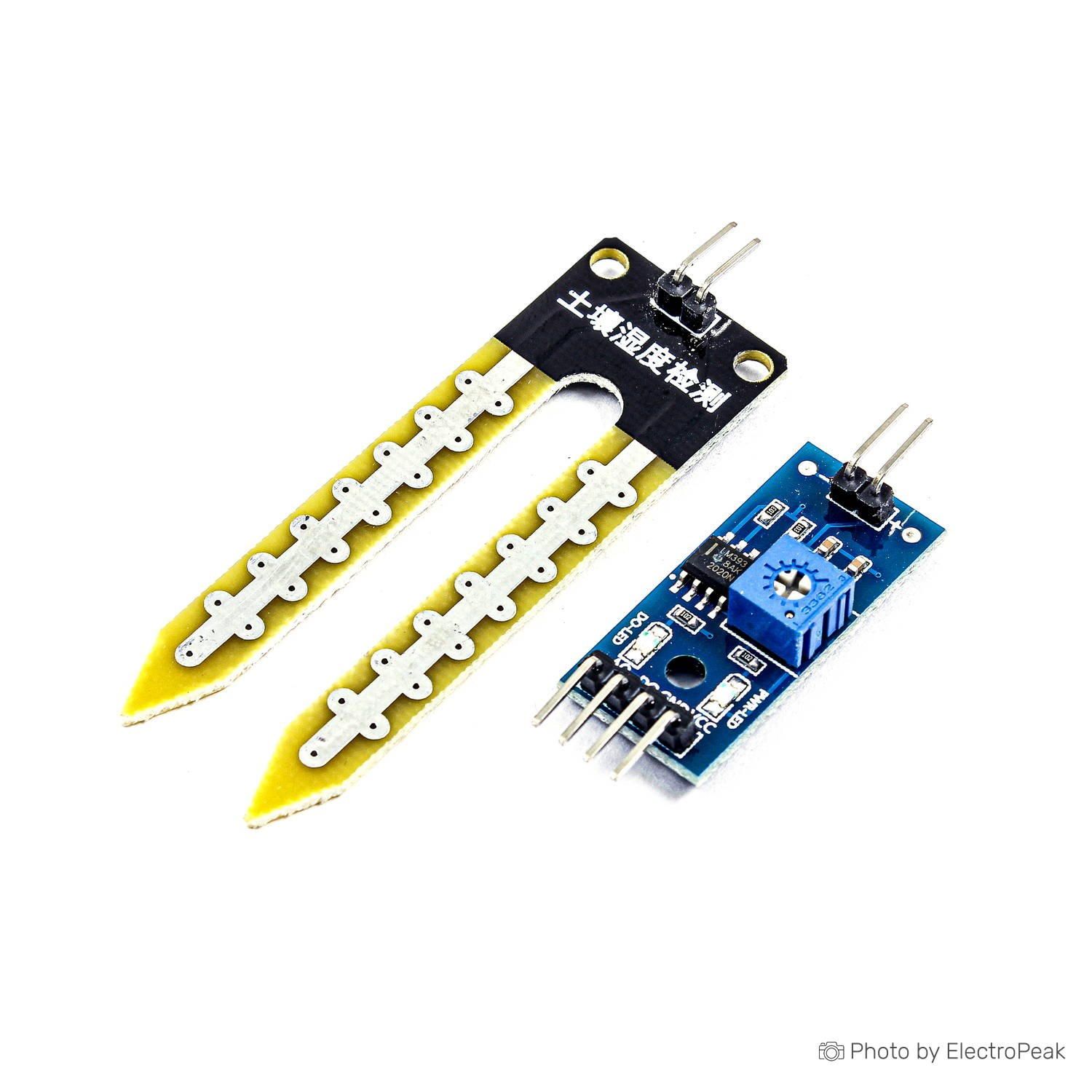
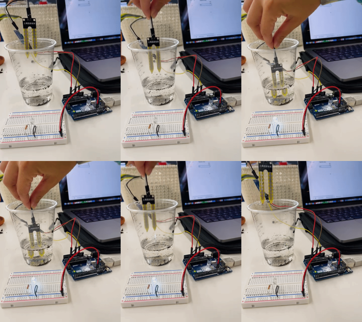
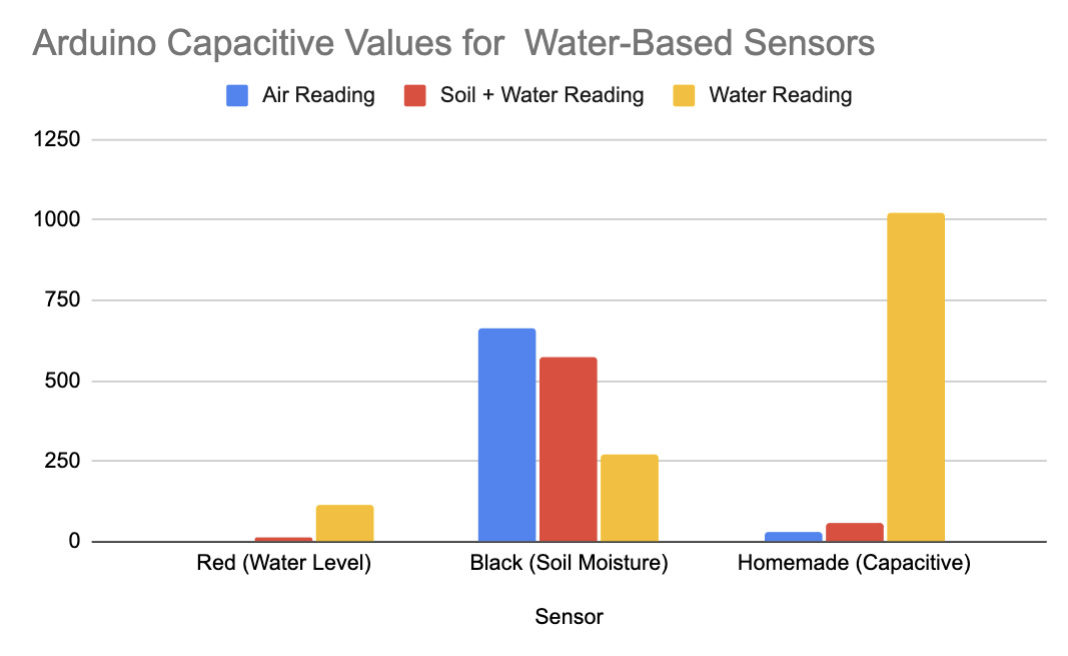
Thankfully, we can confirm that this sensor was, in fact, meant to measure soil moisture. Because we tried this sensor after trying our homemade sensors, the plant's soil was already very wet. So we decided to just take the main three measurements. The downward slope from air, to plant, to water aligns with the assumption that the sensor value decreases as more moisture is detected.
Arudino Code & Process
int sensorPin = A0;
int sensorValue;
int limit = 300;

void setup() {
    Serial.begin(9600);
    pinMode(13, OUTPUT);
}

void loop() {

    sensorValue = analogRead(sensorPin);
    Serial.println("Analog Value : ");
    Serial.println(sensorValue);

    if (sensorValue < limit) {
        digitalWrite(13, HIGH);
    }
    else {
        digitalWrite(13, LOW);
    }

    delay(1000);
}
| Experiement | Capacitive Value (Arduino) |
|---|---|
| Exposed to air | 663 |
| Submerged in water | 273 | Stuck in plant | 574 |
Experiment Takeaways (?)
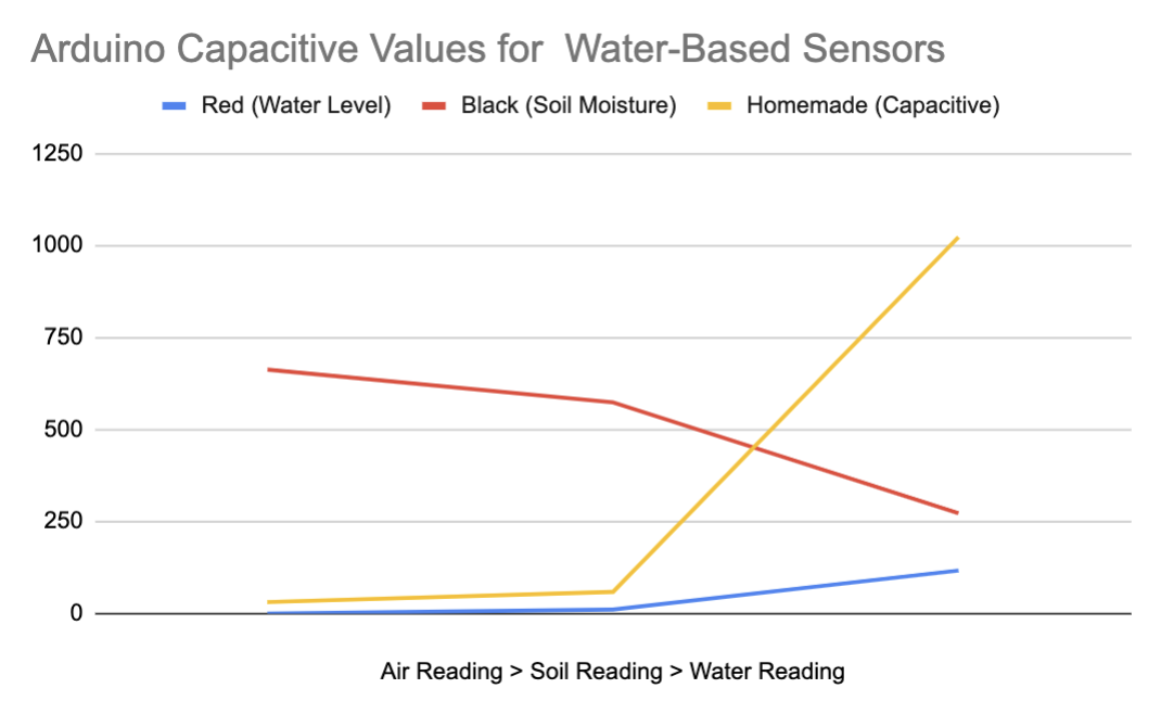
My primary takeaway from this exercise is that there's a lot you can do with sensors in regard to the natural world. It's also important to note that different sensors use different capacitive values in Arduino, which theoretically you could calibrate/standardize across different sensor types. However, I don't think we designed this experiment as thoughtfully as we should have. This was partially because we did not know the origin or use case of all the sensors we found in the lab, instead using them in a trial & error capacity. I think this was fine for the purpose of this week's assignment, but we need to be careful and precise for future sensor-based prototypes.
| Sensor | Air (no water) | Soil+Water (some water) | Water (most water) |
|---|---|---|---|
| Red (water level) | 0 | 11 | 117 |
| Black (soil moisture) | 663 | 574 | 273 |
| Homemade (capacitive) | 5900 | 3150 | 102300 |
Sensor Schematics
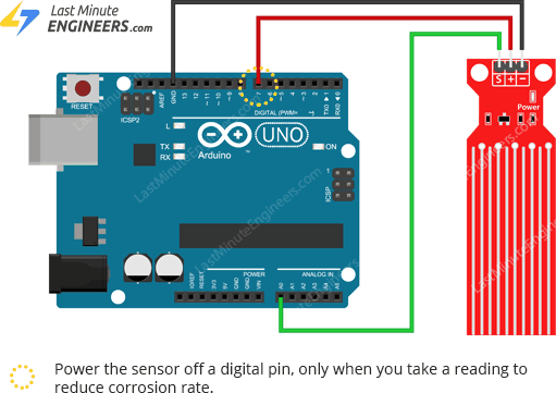
I couldn't find the water level sensor in TinkerCAD, but I found this example circuit online.
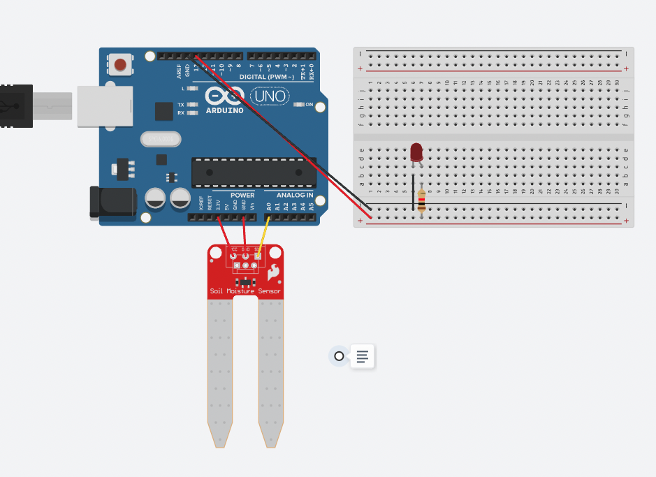
This one was doable online!
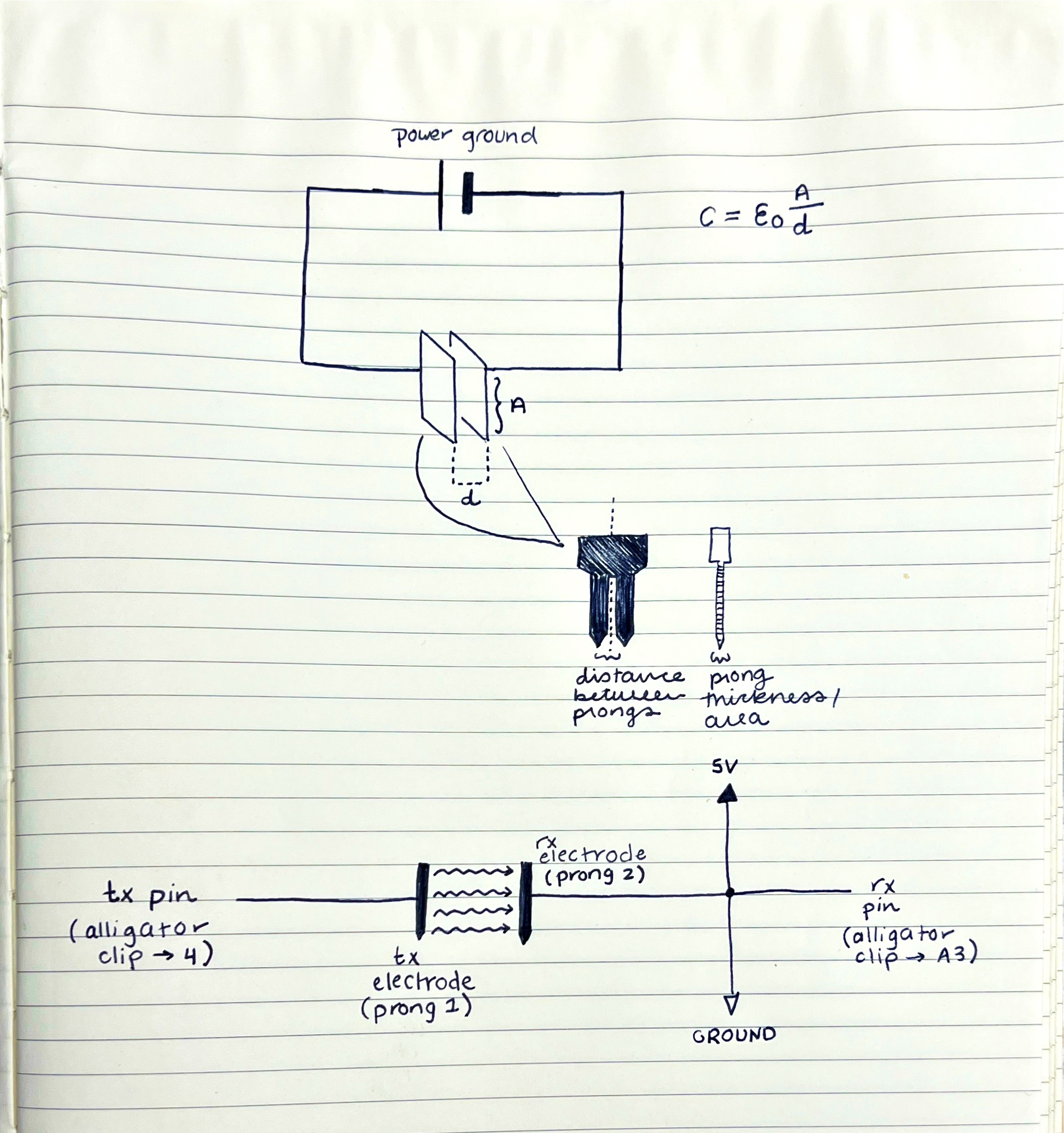
I tried to adapt the tx-rx schematic from the website here.
Photoresistor Tutorial
Ever the curious and unsatisfied overachiever, I wanted to try out a different electronic input device. I found a tutorial for connecting a photoresistor (which senses more/less light) to an LED. As the photoresistor reads less light, it triggers the LED to turn on. As the photoresistor reads more light, the LED turns off. The code shows that the light threshhold sits at a value of larger or smaller than 300.
Arudino Code & Process
// determine pin numbers
int ledPin = 13; // LED pin
int photoPin = A0; // photoresistor pin


void setup() {

  Serial.begin(9600);
  pinMode(ledPin, OUTPUT); // LED will be output
  pinMode(photoPin, INPUT); // photoresistor will be input

}

void loop() {

  int photoStatus = analogRead(photoPin); // read the status of the photoresistor

  // check if the photoresistor status is less than 300
  // if it is, the LED is HIGH

  if (photoStatus < = 300){
    digitalWrite(ledPin, HIGH);
    Serial.println("Photoresistor is dark, LED is on.");
  }

  else {
    digitalWrite(ledPin, LOW);
    Serial.println("......");
  }
}